
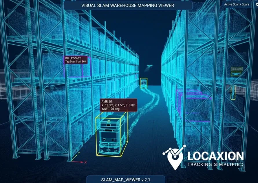
- How it works, types of SLAM, and its applications
- What is SLAM (What the acronym actually means)
- How does SLAM work: The core algorithmic loop
- Visual SLAM vs. LiDAR SLAM: Choosing the right sensor layer
- SLAM Technology in RTLS System Design
- Implementing Vision-Based RTLS with SLAM
- Where SLAM-Based RTLS Is Being Applied
- Limitations of SLAM technology (Worth understanding before you commit)
- FAQs on SLAM technology
- Conclusion
How it works, types of SLAM, and its applications
Most indoor location tracking systems are built around a fixed-infrastructure premise: place reference points throughout a facility, calculate position by triangulating against those known coordinates, and accept that the quality of the result depends on how well those reference points are installed and maintained. SLAM technology approaches the same problem from a structurally different direction, as it maps the environment and determines position within that map at the same time, using sensor data alone, without pre-installed anchors and without prior knowledge of the space.
For organizations evaluating real-time location technology for warehouses, manufacturing facilities, or other GPS-denied environments, that architectural difference carries real implications, like: for infrastructure cost, deployment complexity, operational flexibility, and long-term maintenance burden. This article works through what SLAM technology is, how it functions as the position engine of a vision-based RTLS, and where the approach performs well and where it does not.
What is SLAM (What the acronym actually means)
SLAM stands for Simultaneous Localization and Mapping. The acronym is unusually literal: it describes the core problem rather than the solution. A system needs to determine where it is (localization) within an environment it is simultaneously engaged in building a map of — in real time, from sensor data alone.
That circularity is the fundamental challenge of SLAM. Accurate mapping requires knowing where you are. Knowing where you are requires a map. The class of algorithms collected under the SLAM label resolves this dependency by treating the map and the position estimate as jointly uncertain states that are updated continuously as new sensor observations arrive, rather than solving either problem first and using the result to address the other.
What does SLAM stand for in the broader context of its history?
The concept emerged from robotics research in the late 1980s and early 1990s, framed as the problem of enabling autonomous mobile robots to navigate unfamiliar environments without external reference infrastructure. The probabilistic mathematical formulations developed during that period, using filters to represent and propagate uncertainty in both position and map state, remain the conceptual foundation of how SLAM technology operates today, even as the computational implementation has changed substantially with available processing power and sensor hardware.
What is SLAM technology when it moves from research robotics into operational RTLS?
In practice, it is a software layer that continuously processes sensor input from cameras or LiDAR scanners (or combinations of both) to produce a persistent map of an environment and a real-time position estimate within that map. When that layer is integrated into an RTLS architecture, it enables location tracking without GPS signals and without fixed anchor infrastructure, which is what makes it relevant to the class of environments — indoors, underground, GPS-degraded — where most industrial and logistics tracking requirements actually exist.
How does SLAM work: The core algorithmic loop
Understanding how SLAM works at a functional level matters for RTLS deployment planning because the algorithm's behavior under different environmental conditions directly determines where a SLAM-based system will perform reliably and where it will encounter limits worth designing around.
At its operational core, a SLAM system runs a continuous loop of four interdependent processes:
- Sensor input acquisition The system reads data from its sensor configuration, camera frames in a visual SLAM implementation, geometric point clouds in a LiDAR implementation, or combined data streams in multi-modal systems. Each reading represents the environment as observed from the system's current position at a specific moment in time.
- Feature extraction and matching The system identifies distinctive characteristics in the sensor data, i.e., edges, corners, textured surfaces, geometric structures, planar regions, and matches them against features observed in prior sensor readings. This matching is what allows the system to recognize that it has returned to a previously mapped area, even as the total map continues to expand. The quality of the feature extraction and matching process is one of the primary variables that differentiates SLAM implementations in practice.
- State estimation Using the feature matches and any additional motion data available from wheel odometry, inertial measurement units, or similar sources — the system updates its estimate of its own position and the spatial positions of the features it has mapped. This is the localization component of simultaneous localization and mapping, and it produces the position output that an RTLS system delivers to downstream consumers.
- Map update New features are added to the map; the positions of existing features are refined as additional geometric constraints accumulate from successive observations. The map is not a static product built once and used thereafter — it is a continuously evolving representation of the environment that becomes more accurate and more complete over operating time.
The process that sustains the coherence of this loop over long operating periods and across large map extents is loop closure: the ability to detect when the system has returned to a previously mapped area and use that recognition to correct the accumulated position errors that build up as the algorithm integrates small estimation uncertainties over distance and time. Effective loop closure is computationally demanding, which is why it represents a meaningful differentiator between SLAM implementations when evaluating systems for operational RTLS use. Open-source VSLAM frameworks such as ORB-SLAM3 and RTAB-Map each address loop closure differently, and the distinction has practical implications for localization accuracy in large-scale indoor environments. [External link: ORB-SLAM3]
Visual SLAM vs. LiDAR SLAM: Choosing the right sensor layer
SLAM is an algorithm family, not a sensor specification. The simultaneous localization and mapping approach can be implemented with several different sensor inputs, and the sensor choice has consequential implications for system design, deployment cost, and operational performance. For vision-based RTLS specifically, the relevant comparison is between visual SLAM and LiDAR SLAM.
- Visual SLAM (VSLAM) It uses camera sensors (monocular or single lens, stereo or dual lens providing depth through disparity, or RGB-D color combined with active depth measurement) as the primary sensor input. The main advantages are hardware cost (cameras are substantially less expensive than LiDAR units at comparable quality tiers), information density (camera frames capture rich texture, color, and semantic content that supports robust feature matching), and the ability to exploit appearance-based loop closure in textured environments. The operational constraints are sensitivity to lighting conditions, performance degradation in low-texture or highly repetitive environments (uniform shelving runs, blank concrete walls), and the computational demands of processing high-resolution image streams at the update rates RTLS applications require.
- LiDAR SLAM This uses laser rangefinders to capture precise geometric point clouds of the surrounding environment. LiDAR is significantly more robust to lighting variation, performs well in low-texture environments where visual feature extraction struggles, and produces geometrically accurate maps with high spatial consistency. The trade-offs are hardware cost as LiDAR units remain meaningfully more expensive than cameras and reduced semantic richness in the raw sensor data.
For vision-based RTLS implementations in industrial and logistics facilities, Visual SLAM represents the more cost-accessible entry point, and algorithmic advances over the past decade have substantially improved VSLAM reliability in structured indoor environments with adequate environmental texture. The conditions under which Visual SLAM performs most predictably: consistent illumination, sufficient surface texture, moderate rates of environmental change, which describe a large proportion of warehouse, manufacturing, and distribution environments. Where those conditions are not reliably met, a hybrid approach that combines VSLAM with depth sensors or supplements with sparse LiDAR may provide the necessary robustness.
SLAM Technology in RTLS System Design
When SLAM technology serves as the position engine for an RTLS deployment, it shifts the architectural requirements of the system in ways that are worth understanding before integration design begins.
A conventional anchor-based RTLS — using BLE, UWB, or similar RF technologies — is infrastructurally intensive: anchors must be specified, placed, surveyed, powered, and maintained across the facility, and location accuracy is shaped largely by anchor density and placement geometry. Position is calculated in the anchor network, relative to known fixed coordinates. SLAM-based RTLS inverts this arrangement: the environment itself becomes the reference frame, the map is built from sensor observations rather than pre-surveyed anchor positions, and the position calculation runs in the moving sensor platform relative to the accumulated map.
In an operational warehouse context, this has several practical implications worth itemizing:
- There is no fixed anchor infrastructure to design, procure, install, or maintain.
- The system can be deployed in spaces where cable runs or anchor mounting are impractical due to ceiling height, environmental conditions, or structural constraints.
- The map can be updated as the physical environment changes, without requiring anchor repositioning or full-system recalibration.
- The location data produced — position coordinates expressed within the SLAM map's coordinate frame — can be ingested by a WMS, ERP, or digital twin platform in the same way that anchor-based RTLS output would be.
The design decisions that define a SLAM-based RTLS deployment include: the sensor specification and placement on the assets or vehicles being tracked; the edge or cloud compute infrastructure that runs the SLAM algorithm at the required update rates; the coordinate system alignment between the SLAM map and the facility floor plan used by downstream systems; and the strategy for map initialization, versioning, and ongoing maintenance as the physical environment evolves. Each of these decisions has dependencies on the others, which is why SLAM-based RTLS system design benefits from being treated as an integrated engineering problem rather than a sequential component procurement exercise.
Implementing Vision-Based RTLS with SLAM
Implementation of a vision-based RTLS built on SLAM technology follows a sequence that differs from anchor-based RTLS in several important respects. Getting the sequence right determines whether the system reaches its designed performance level within a reasonable timeline.
- Map initialization Before position tracking begins, the SLAM system must construct an initial map of the environment. This is done by moving a sensor-equipped platform through the full operational area — either manually or using the tracking vehicle itself — while the algorithm builds its initial representation. In a complex facility with multiple zones, varied ceiling heights, and areas of limited visual texture, this process requires careful path planning to ensure complete coverage and sufficient environmental overlap for the loop closure algorithm to function correctly.
- Localization validation Once an initial map exists, the system's ability to localize new sensor observations against it must be evaluated across the full mapped area. This phase identifies zones where the environment lacks sufficient distinguishing features for reliable localization — areas where estimated position uncertainty exceeds the application's accuracy requirements — and informs design adjustments: adding visual landmarks, modifying camera placement, adjusting illumination, or supplementing with additional sensor modalities in affected zones.
- Downstream SLAM integration Position data from the SLAM layer must be formatted, time-stamped, and delivered to the systems that consume it. This involves defining the coordinate system in which positions are expressed, mapping that coordinate system to the floor plan geometry used by the WMS or digital twin, and establishing the refresh rate and latency characteristics the downstream systems require. Integration design at this stage also covers how position uncertainty is represented and communicated to consumer systems — a consideration that anchor-based RTLS implementations rarely need to address explicitly.
- Map maintenance with SLAM Warehouse and manufacturing environments change: racking configurations shift, new equipment is introduced, temporary structures appear and disappear. A SLAM map accurate at deployment diverges from the physical environment over time, and that divergence introduces localization errors in the areas of greatest change. Map maintenance strategy — the frequency and process for map updates, the procedure for validating updated maps before they replace prior versions, and the system's behavior in areas where the live environment has diverged from the stored map — is a system design requirement that must be addressed explicitly and is frequently underweighted in initial SLAM-based RTLS planning.
Where SLAM-Based RTLS Is Being Applied
SLAM technology in RTLS has moved beyond proof-of-concept into operational deployments across a range of sectors, each with distinct requirements that the infrastructure-light nature of SLAM addresses differently.
- Warehouse and logistics: Autonomous mobile robots used for goods-to-person picking, inventory scanning, and material transport use SLAM — typically LiDAR-based — as their primary navigation layer. Vision-based RTLS is increasingly being evaluated for tracking non-autonomous assets within the same environments: forklifts, pallet jacks, carts, and inventory locations at granularities below what RF-based systems can consistently deliver. [External link: MHI Annual Industry Report]
- Manufacturing and industrial facilities: Complex, GPS-denied manufacturing environments — where anchor installation is constrained by RF interference risk, ceiling structure, or operational layout density — represent a natural application for SLAM-based location. Equipment tracking, tool location management, and personnel safety zone monitoring in these environments benefit from deployment approaches that do not require fixed infrastructure planning before the system can be used.
- Healthcare industry: Asset tracking in clinical environments has demanding requirements: room-level or bay-level accuracy, minimal physical infrastructure footprint, and compatibility with clinical-grade connectivity and hygiene standards. Visual SLAM-based systems are being evaluated as alternatives to RFID and BLE anchor networks in facilities where infrastructure installation is constrained by building structure, infection control requirements, or the operational disruption that installation would cause.
- Construction and infrastructure projects: Temporary, rapidly changing environments are where SLAM-based RTLS has the most structural advantage over infrastructure-dependent alternatives. Equipment tracking on active construction sites, progress documentation through periodic visual mapping, and safety perimeter enforcement in dynamic worksites are application areas where the inability to pre-install fixed anchors is not a deployment constraint but a defining condition.
Limitations of SLAM technology (Worth understanding before you commit)
SLAM technology in RTLS is capable, and it is also constrained in ways that matter for deployment decisions. Understating those constraints at the evaluation stage is one of the more reliable paths to an implementation that fails to meet expectations.
- SLAM in dynamic environments SLAM algorithms assume, by default, that mapped features are static — that the wall observed last month remains where the map records it. In environments with significant dynamic content — moving people, repositioned goods, vehicles in transit — the algorithm must distinguish between moving objects and stable map features. The quality of that distinction varies between implementations and is one of the factors that should be directly evaluated for any environment where high traffic density is a permanent condition.
- Lighting sensitivity in visual SLAM Camera-based implementations depend on adequate, consistent illumination to extract reliable features. Facilities with highly variable natural light, significant dark zones, or high-glare reflective surfaces require photometric analysis during system design, and may require lighting modifications in affected areas. This is not an obstacle to deployment; it is a design input that needs to be captured and addressed.
- Computational load in SLAM algorithm Running a SLAM algorithm at the position update rates required for operational RTLS — with active loop closure — demands meaningful edge compute resources on the tracked vehicle or in nearby infrastructure. This represents both a hardware cost and a system maintenance requirement that differs from those of a conventional anchor network.
- Map drift and version governance using SLAM Accumulated position estimation errors over long trajectories or large map extents require active management. In operational deployments, map governance procedures — defining who updates the map, how updates are validated, and how the system behaves in areas of map-environment mismatch — must be established as operational processes, not treated as one-time deployment tasks.
None of these constraints disqualify SLAM-based RTLS for the environments where it is well suited. They are relevant precisely because understanding them at the evaluation stage is what allows the implementation to be designed around them effectively.
FAQs on SLAM technology
What does SLAM stand for?
SLAM stands for Simultaneous Localization and Mapping. It builds a map of an environment and determines position within that map at the same time, using only sensor data, without prior knowledge of the space or external reference infrastructure.
What does the SLAM method stand for in a technical context?
In technical literature, the SLAM method refers to the class of algorithms that jointly estimate two unknowns — a map of an environment and the position of a sensor within it — as a probabilistic inference problem. The "simultaneous" in simultaneous localization and mapping captures the key insight: neither the map nor the position estimate can be determined independently of the other, so both are updated together as new sensor observations arrive and reduce uncertainty in the joint state.
How does SLAM work in a real operational environment?
SLAM works by continuously reading sensor data from cameras or LiDAR, identifying and matching environmental features, and updating both its position and map in real time. Loop closure helps correct drift by recognizing previously visited areas, keeping localization accurate over longer operation.
What is SLAM technology used for in warehouse RTLS?
In warehouse RTLS, SLAM technology enables infrastructure-light location tracking: forklifts, autonomous mobile robots, pallet jacks, and other assets carry camera or LiDAR sensors that determine their position within a SLAM map of the facility, without requiring BLE or UWB anchors distributed throughout the space. The position data integrates with WMS, ERP, and digital twin platforms through the same interfaces that anchor-based RTLS data would use.
How is SLAM technology different from traditional RTLS?
Traditional RTLS — BLE, UWB, RFID-based — determines position by triangulating against known, fixed reference points installed throughout the facility. SLAM technology determines position by matching sensor observations against a map the system built from its own sensor data, without fixed infrastructure. The trade-offs are: anchor-based systems have predictable infrastructure costs and straightforward accuracy models; SLAM-based systems eliminate fixed infrastructure at the cost of greater computational requirements, environmental sensitivity, and map governance complexity.
Can SLAM-based RTLS operate without GPS?
Yes, this is one of the primary reasons SLAM technology is relevant to indoor RTLS. The algorithm operates entirely on local sensor data and builds its reference frame from the environment itself, without any dependence on external positioning signals. GPS-denied environments i.e., indoors, underground, in RF-noisy industrial settings, are precisely the contexts the technology was designed to address.
Conclusion
SLAM technology represents a genuine architectural alternative to fixed-infrastructure RTLS, one that trades anchor installation and maintenance overhead for computational requirements, environmental sensitivity, and map governance complexity. For environments where that trade is favorable, vision-based RTLS built on SLAM enables location tracking capabilities that anchor-dependent systems cannot easily replicate, at an infrastructure cost that is meaningfully lower.
The operational conditions that suit SLAM-based RTLS are specific enough to require honest evaluation rather than adoption driven by the technology's novelty or the elegance of the underlying algorithm. Computational load, environmental dynamics, lighting characteristics, and map versioning requirements all influence whether a given deployment will perform as designed over its operational lifetime.
LocaXion works across the RTLS technology landscape — anchor-based, vision-based, and hybrid — from a technology-agnostic position. If you are evaluating slam technology for an indoor tracking application and want an assessment grounded in your specific operational environment rather than a vendor's preferred approach, that conversation starts with the environment, not the algorithm.